Radio alarm clock

This circuit is a simple to use radio alarm clock. The radio itself is not described,
only the alarm device.
The advantages of this radio alarm clock are:
- No need for backup battery, alarm times and settings are backupped in EEPROM.
- Time is automatically adjusted using DCF77 radio signals. This works only in Europe.
- Current time and alarm times are visible together, no need for switching.
- Operated using touch buttons.
- Sleep timer, snooze function and up to 2 alarm times.
- Big character display (6 x 1.5 cm) with choice of 3 different fonts.
- LCD display with backlight, automatically adjusted to the ambient light conditions.
- If you like, the alarm will not work in the weekends.
- For alarm, you have the choice of sounding a built in buzzer, operating the built in radio or operating an external
device (e.g. cd player, tv etc.).
The program makes use of the built-in AD converter of the PIC16F874 for sensing the touch buttons.
The PIC has 8 AD ports, seven are used for the 7 touch-buttons, 1 is used for the light measurement.
In order to receive DCF signals, you have to add a DCF module (e.g. Conrad nr. 641138 - 89) which will
provide a digital TTL level DCF signal which is than interpreted by the software to automatically adjust
the time.
If you use the Conrad module, pin 1 of this module goes to ground, pin 2 to +5VDC and
pin 3 (DCF-out) to pin 6 of the PIC.
For the LCD display, a standard Hitachi 44780 compatible LCD module can be used, as long as it has 20 x 4
characters and LED backlight.
The backlight of the LCD can be dimmed either manually or automatically, proportional to the ambient light. This is
done using an LDR as a light sensor and the PWM capability of the microprocessor.
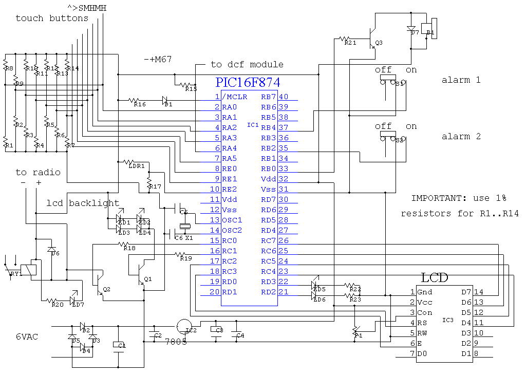
Schematic diagram of the radio alarm clock

List of components
Circuit explanation:
The LCD display is connected to PORTC. An LDR/resistor voltage dividor serves as a light sensor, which
adjusts the background lighting of the LCD according to the ambient light if desired. Note the simple construction
of the touch buttons: the user's finger must touch the middle of a voltage divider connected to the analog ports,
which causes slight fluctuations in voltage. The software will then decide if a button is touched or not.
Not shown on the diagram: the connections of the relay to the external device (cd player etc.) and the power supply
transformer. Just do this the way you want.
Source code for this project
Features/short user manual (PDF file)
Pseudo code (Word 2000 document)
Picture's

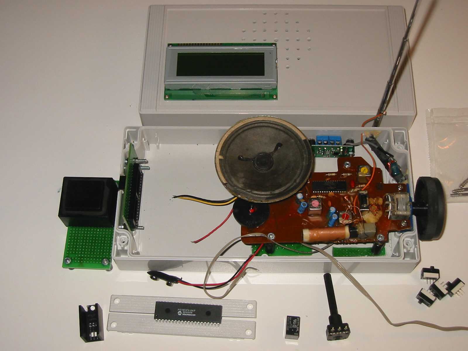
The device not finished yet, radio already mounted, some other parts swinging around.
|

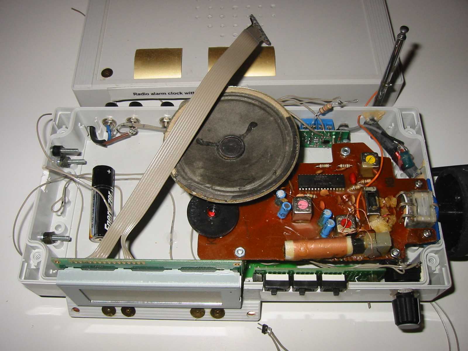
In the second stage: some buttons, touch-buttons and display are now there.
|

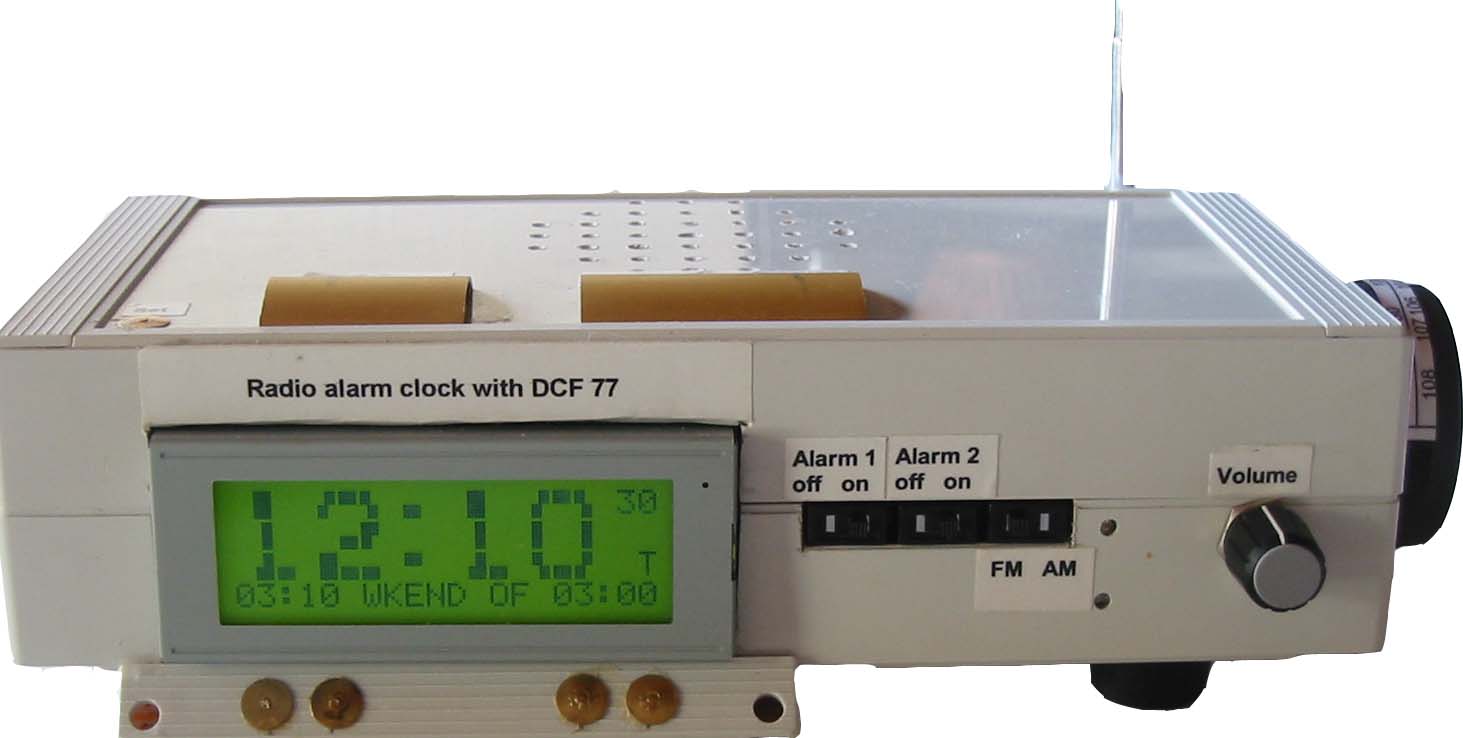
The finished device. The touch-buttons are just plain old 'thumbnails' and other peaces of metal.
|
 Home
Home
 Back to Electronic Projects


