Various car alarm extensions
1. Car alarm hazard signal extension

Extension for a car-alarm system. This circuit, together with the software, signals when you set the alarm on or off. When the alarm is on, it also signals if there has been a burglar attempt (the number of attempts is counted). When putting off the alarm, the circuit will let the user know how many number of burglar attempts there have been (using the turn-signals or a speaker).
Source code
2. Car alarm hazard signal extension, new version
New version of the car alarm hazard signal extension, this one does not count the number of burglar attempts but it has some other interesting features:
- zero power consumption in standby mode
- produces two different patterns for alarm off and alarm on, very nice flip/flop effect (left and right turning bulbs powered separately)
- no interference with existing flasher relay, this is turned off during operation
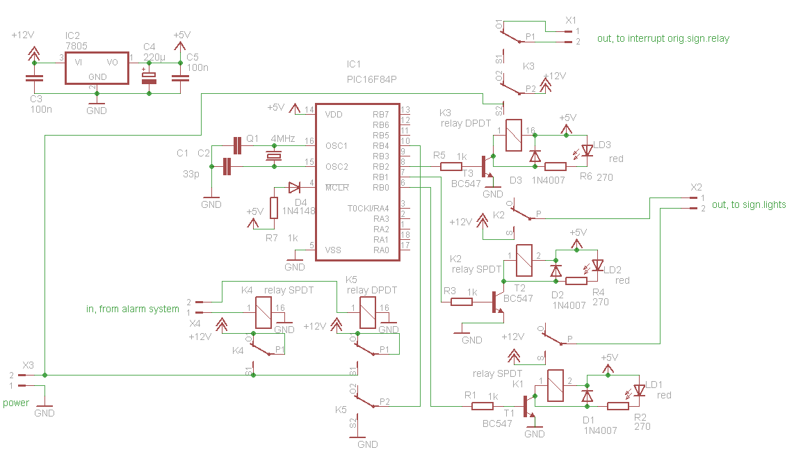
Connections:
X3: power (1 = ground, 2 = +12V always hot)
X4: input, from alarm system, when a short pulse of 12V is applied to pin 1, the turning lights will flash in a pattern to indicate the alarm is now "on".
Pin 2 is for "alarm off".
X1: (optionally) interrupt, this is to interrupt the power to the original flasher relay system of the car, to prevent damage to the original system when this device is working
X2: output to turning light bulbs, 1 = left, 2 = right
3. Interface Velleman remote/central locking/alarm
This is just a "connection box" to connect several systems together. It is designed to suit my specific situation. Following systems can be connected to this device:
- Velleman VM130 remote receiver (device that receives signals from a remote control, used to open car doors, set alarm on/off etc.)
- Car alarm hazard signal extension, see above
- Flashing LED to indicate "alarm on"
- A retrofitted central locking system, e.g. the ML22 from Waeco
- An alarm system
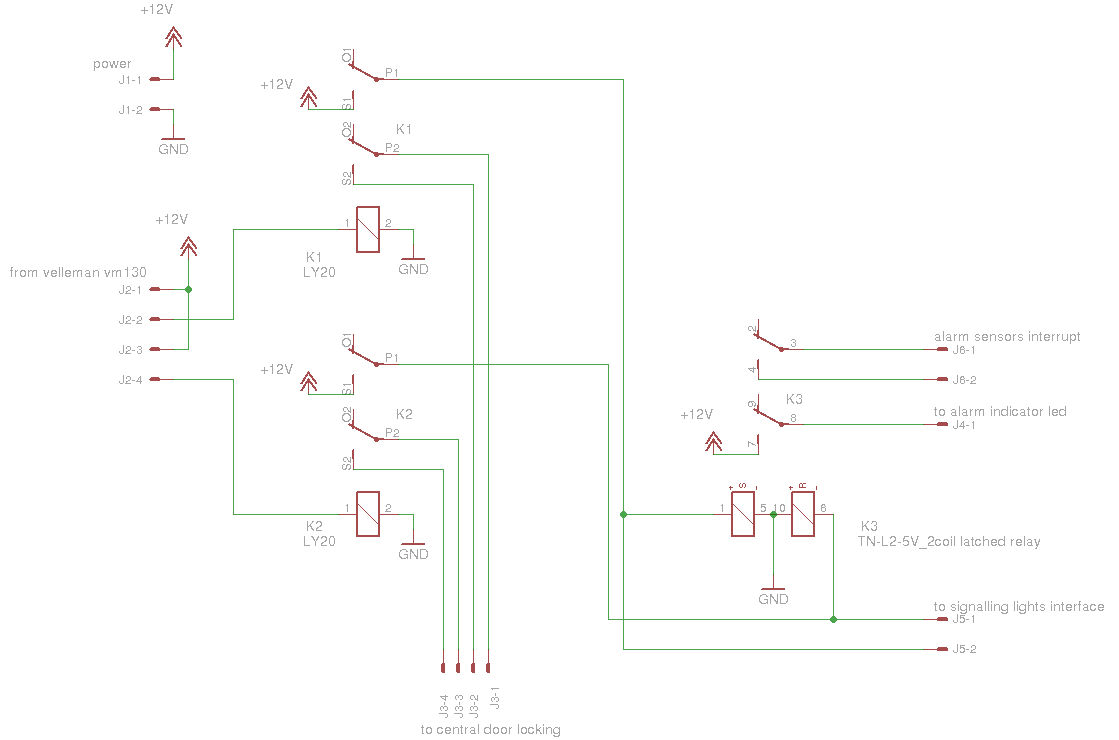
Connections:
J1: power (1 = +12V always hot, 2 = ground)
J2: to connect to Velleman VM130 remote receiver
J3: to connect to a central door locking system, e.g. Waeco ML22 (1/2 = open door, 3/4=close door)
J4: flashing LED output (12V)
J5: to signalling lights interface (see above) (1 = alarm on, 2 = alarm off)
J6: to alarm system (1 and 2 are closed when alarm must go on)
4. Flashing led
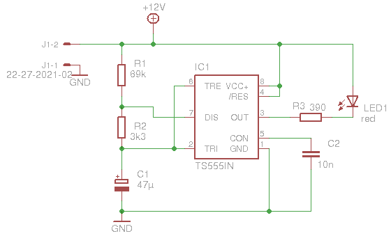
A simple led flasher using a CMOS 555 timer using very low power. The LED is connected from +12V to the 555's output, to save power and to invert the duty cycle. The LED flashes every 2 seconds for about 100 ms (5% duty cycle).

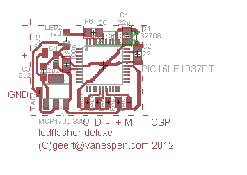
A deluxe version of the led flasher using a PIC16LF1937 consuming very low power. This one first flashes fast for 5 secs (frequency 5Hz duty cycle 50%), then for one minute a little slower (frequency 1Hz duty cycle 20%) and for the rest of the time very slow (frequency 0.5Hz duty cycle 2%). The device operates on 3.3V which is provided by the very efficient MCP1790-3300 voltage regulator.

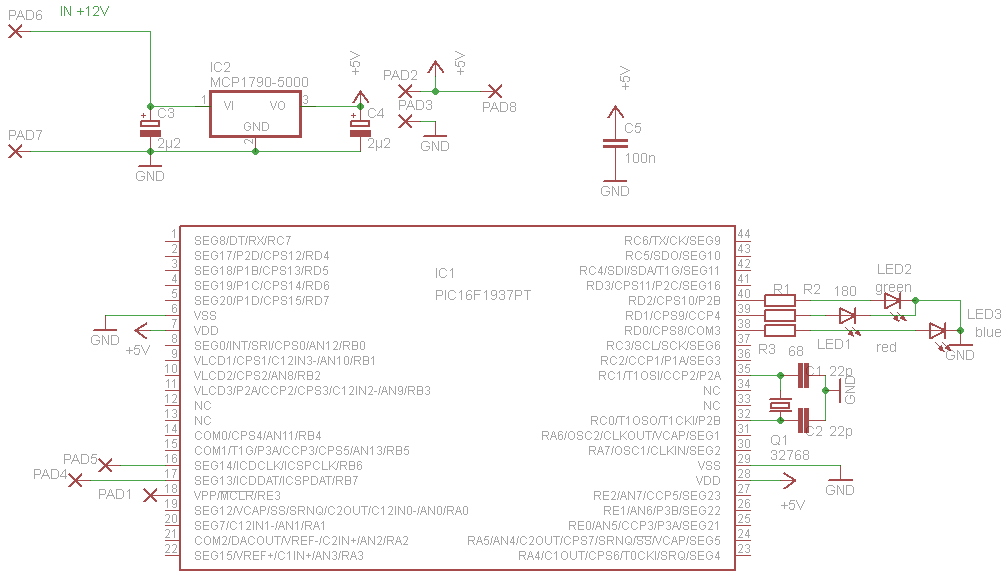
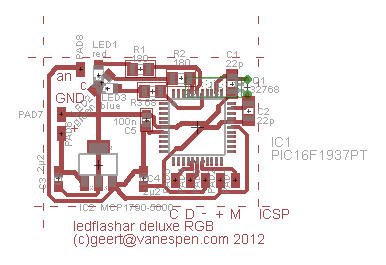
A deluxe RGB version of the led flasher using a PIC16F1937 consuming very low power. This one first flashes fast for 5 secs alternating green, yellow and red (frequency 5Hz duty cycle 50%), then for one minute a little slower alternating cyan and red (frequency 1Hz duty cycle 20%) and for the rest of the time very slow alternating blue and red (frequency 0.5Hz duty cycle 2%). The device operates on 5V which is provided by the very efficient MCP17900-5000 voltage regulator.
