Schematic diagram
Link to PDF file with PCB layout and components setup
Circuit explanation:
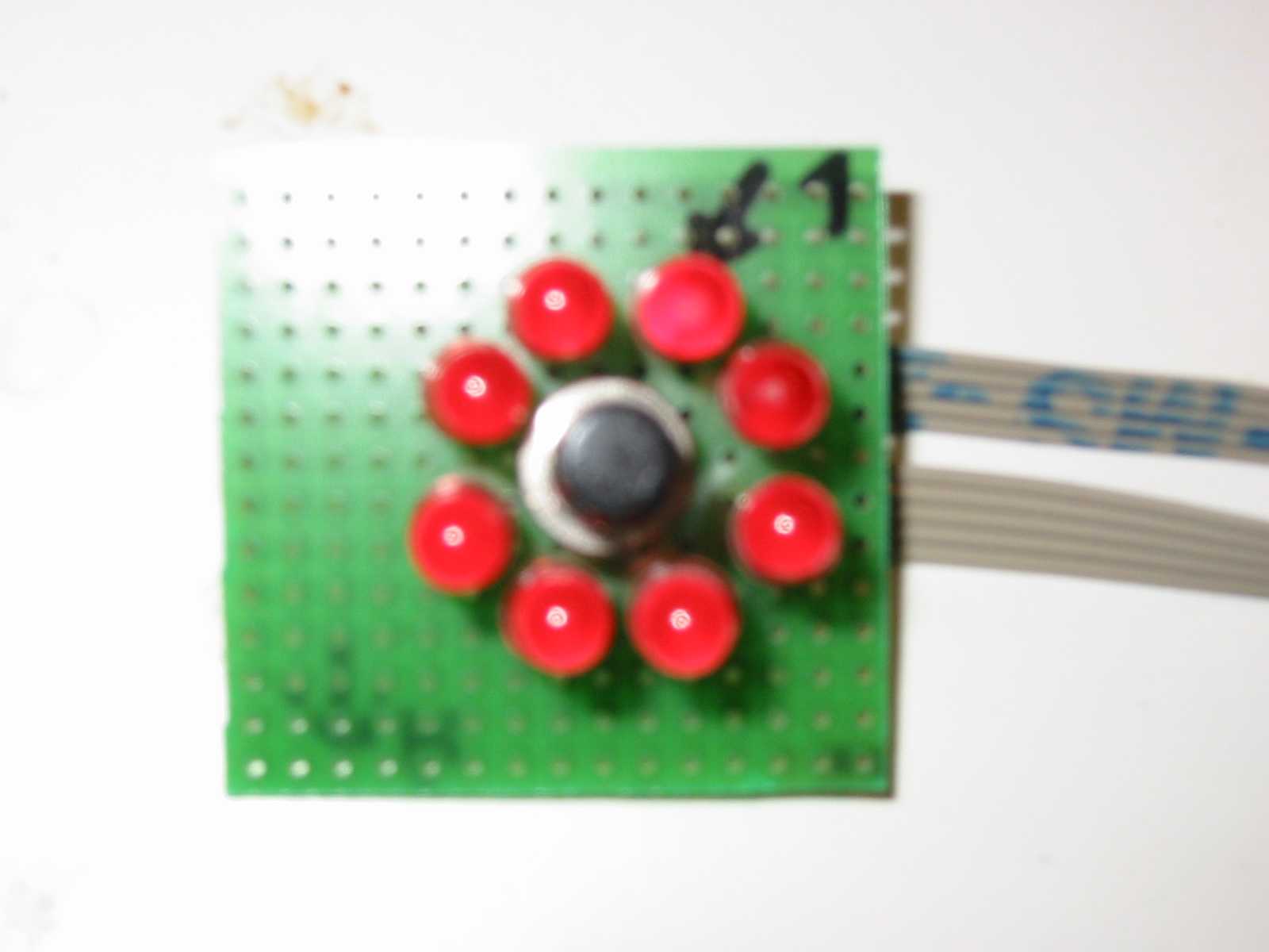
Eight LEDs are connected to ports RB0..RB7 which are configured as outputs. The relay is de-activated at start, so
the user gets power as before (as if the delaytimer was not present). If someone presses the pushbutton, one more
LED is lit. If one or more LEDs are lit, the relay will activate so the power to the user is interrupted. The
countdown starts after the pushbutton is released. Each hour one LED gets off. When all LEDs are off, we are back
to square one (power to the user).
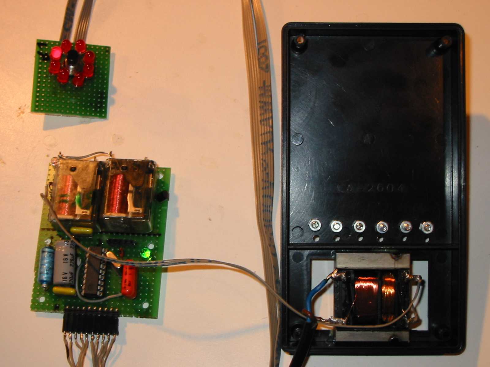
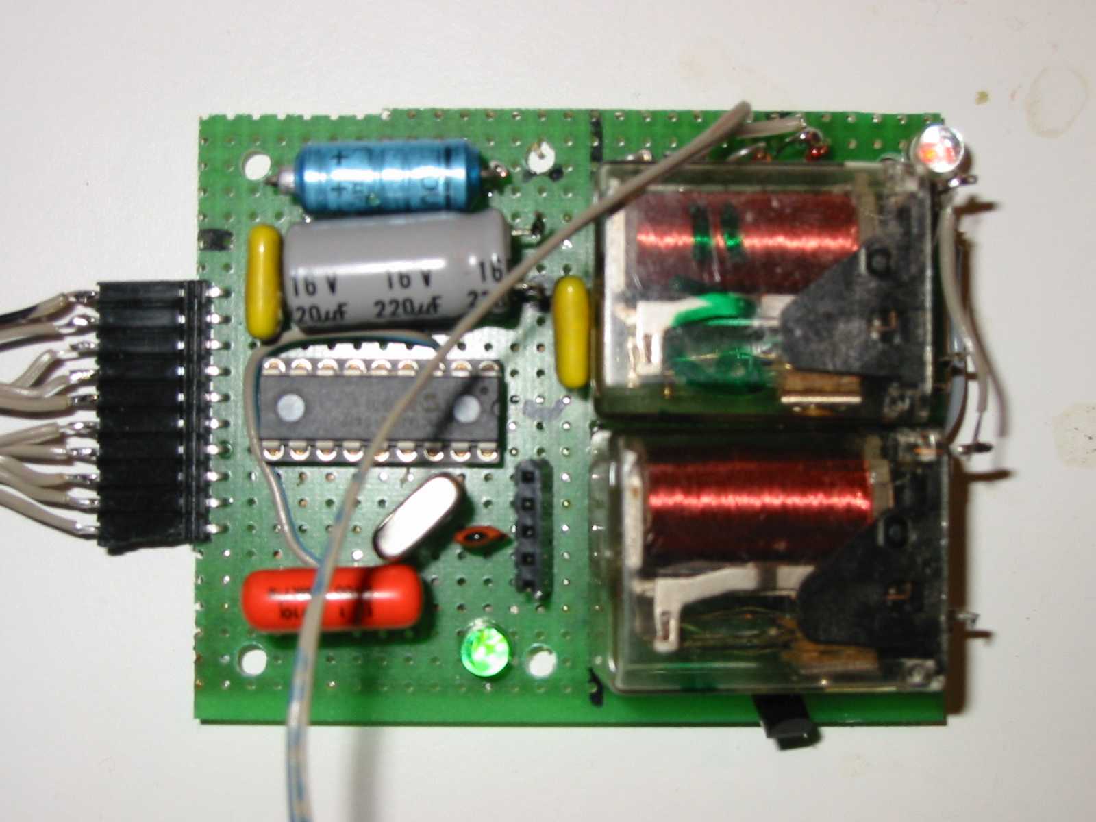
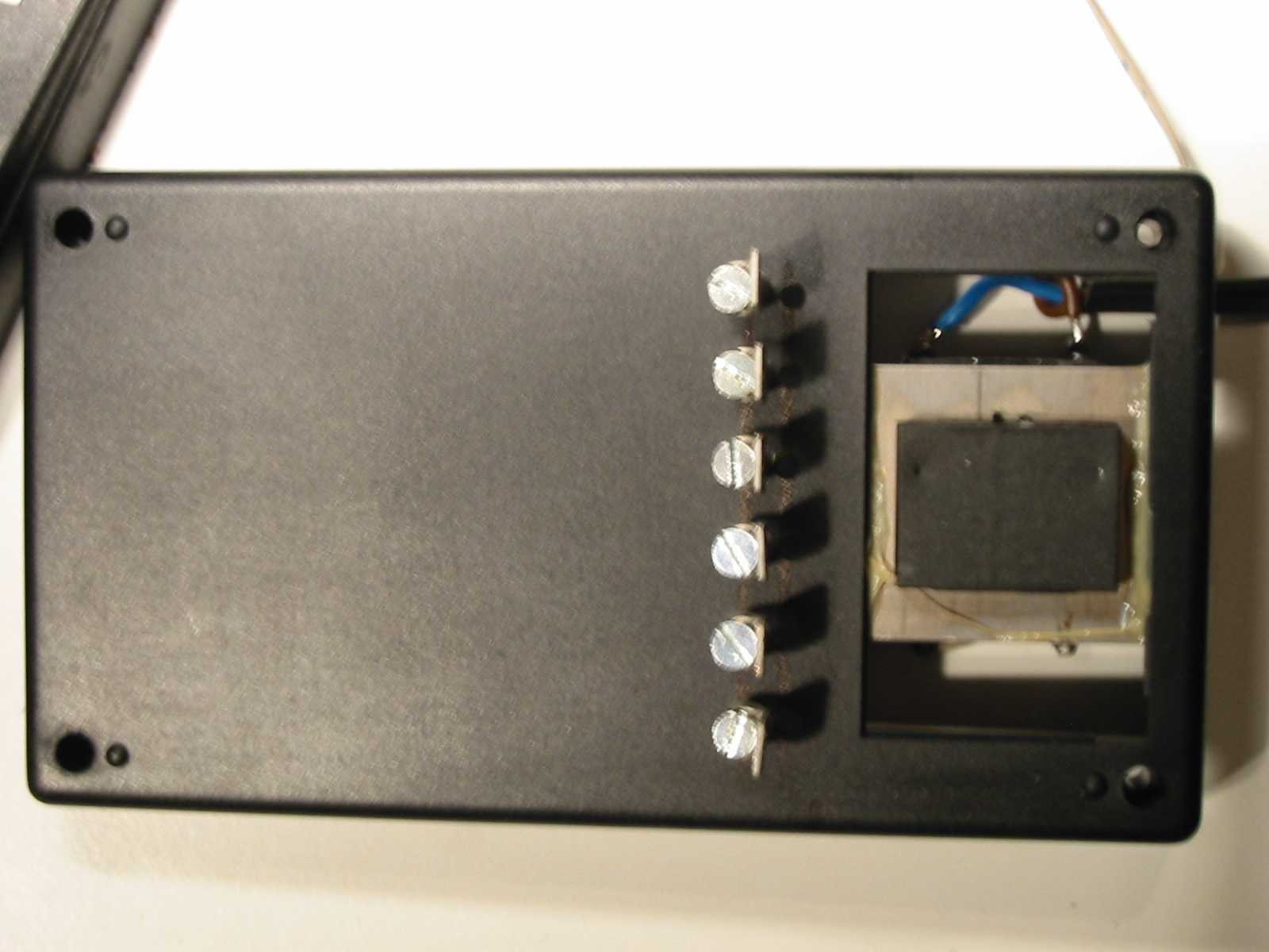
Some pictures:
 |
 |
 |
 |