Electronic dice


This circuit is based around the PIC 16C84 (or PIC 16F84) microcontroller. This chip is actually a small computer contained
in a single chip, including RAM memory, EEPROM, I/O ports, CPU and so on. When you buy this chip, it comes empty with no
program on it. You have to compile the source code and download the resulting machine code into it, using a PC and a small
programmer attached to the parallel port of the PC and the chip. To get yourself familiar with this stuff, I suggest
you first read this link:
Getting started with microcontrollers.
This electronic dice has some nice features: double dice, fade-out effect, auto power off to save batteries. The two
dices are each operated by a push button, which can be pressed simultaneously or separate (multi-tasking techinique
is used to accomplish this). The device is operated on 3 size AAA batteries.
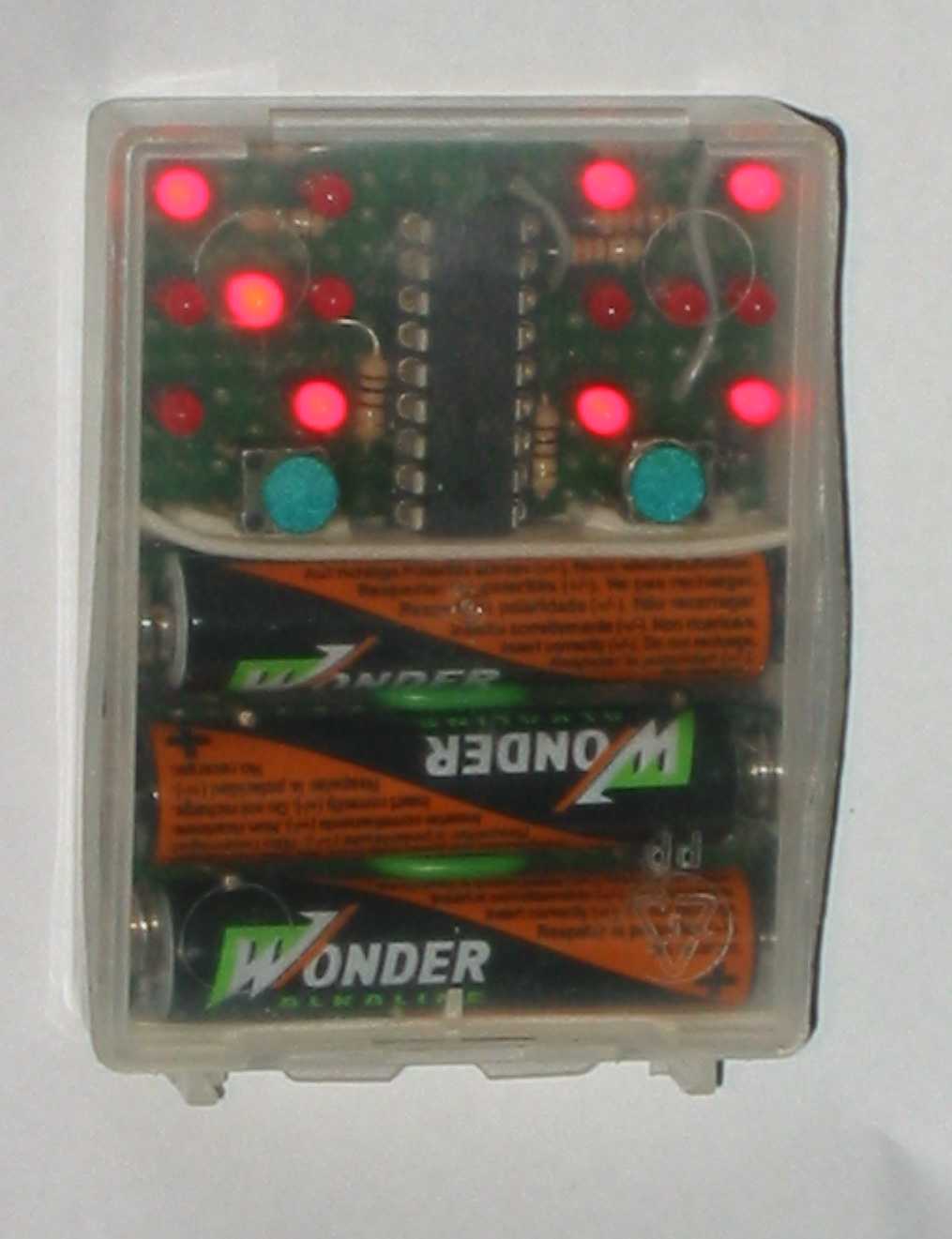
Here is a picture of the finished dice, built into a small plastic box used before to pack nails:

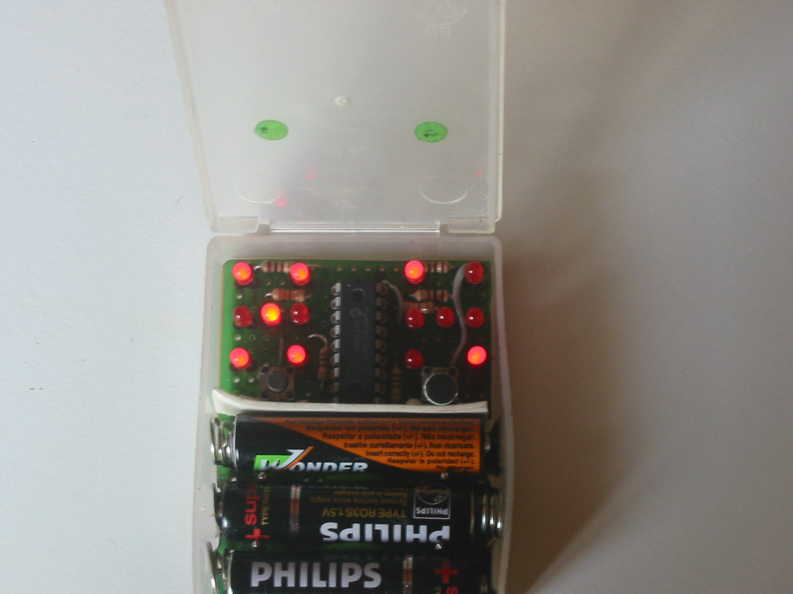
Picture of the case opened:

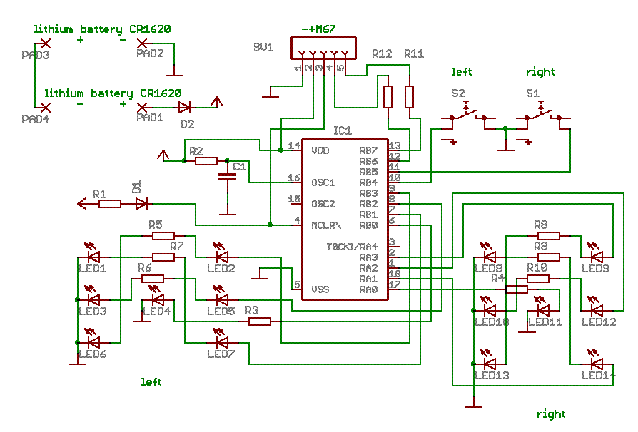
Schematic diagram:
 List of components
Circuit explanation:
It was clearly the intension to build a super-simple circuit and put all the effort in the software, not the
hardware. De LEDs of the left dice are connected to port B, the ones of the right dice to port A, both numbers
0..3. The PIC is used here with an RC oscillator (C1/R2). Both pushbuttons are connected to RB4 and RB5 which is
necessary because only these two inputs can be set to weke up the processor from sleep. In sleep-mode, the
current consumption is in the micro-ampere range, so the batteries can last years without an on-off switch! Then there
are only some resistors for the LEDs, /MCRL to plus via R1 and that's it!
Source code for this project
The SMD version of the dice is here:
 Home
Home
 Back to Electronic Projects


