Car
Flasher Relay
![]()
1.
Introduction
A Car Flasher Relay is used for operating the
flashlights of a car. If you change these lights with LED versions, the flasher
relay will probably not work anymore because
the LEDs use much less power than the original light bulbs. The relay
needs a certain current draw before it starts flashing.
Replacement flasher relays compatible with LEDs are
widely available. So why did I design one of my own? Because I couldn't find a
relay that combines all of the following properties:
-
compatible with BOTH LEDs and classic light bulbs (up
to 100W)
-
4 connectors, one of which is a separate output for
the dashboard indicator
-
produces a customizable sound while flashing
-
customizable flasher frequency
This circuit is based around the PIC 18F2550
microcontroller. This chip is actually a small computer contained in a single
chip, including RAM memory, EEPROM, I/O
ports, CPU and so on. When you buy this chip, it comes empty with no program on
it. You have to compile the source code and download the resulting machine code into it, using a PC and a small
programmer attached to the PC and the chip. To get yourself familiar with this
stuff, I suggest you first read this link: Getting started with microcontrollers.
2.
Description
The device is built around a PIC18F2550 and an LM386 (for
the sound). Basic principle is that the PIC measures the voltage before and
after a shunt resistor which is in series of the light bulbs. When the flasher
handle is in the middle, the lights are not connected, and the voltage before
and after the shunt will be the same. When the flasher handle is either in the
left of right direction, the left or right turning lights are on and there will
be a slight difference in voltage before and after the shunt. This is the
trigger for starting a delay, which will first wait for 400 ms (leaving the
lights lit as they were) and then activate a relay to turn off the lights, also
for about 400 ms. Then the relay is deactivated and at this point the voltage
difference is again measured and if there is still a difference, the cycle
repeats.
3.
Usage/connection
In some cars the connection of the original flasher
relay, bulbs and flasher handle is like this:

The blue rectangle represents the flashing relay
containing the electronics to provide flashing output for the light bulbs,
available on connection “L” and to be distributed by the flasher handle to the
left or right turning bulbs. The “P” output is for an indicator light on the
dashboard. Furthermore the “+” and “-“ are connected to the positive and
negative sides of the car battery.
The circuit described here replaces the original
flashing relay (blue square) and provides all four connections “-“, “+”, “L”
and “P”. In the car electric schematics, these connections are sometimes
referred to as:
-: GND, MASS,
EARTH, 31, C
+: PLUS,
49
L: OUT, LOAD,
49a
P: PILOT,
R, WARN, IND, C2
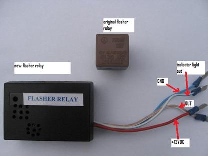
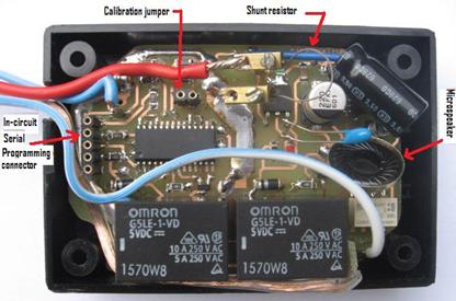
Some pictures of the new flasher relay, a little bit
bigger compared to the original:

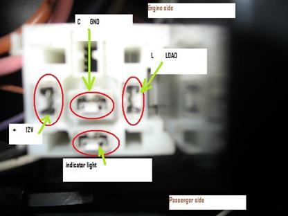
The device is used in my Fiat Ducato camper, all 4
wires plugged in into the original flasher relay socket below the glove
compartment:
4.
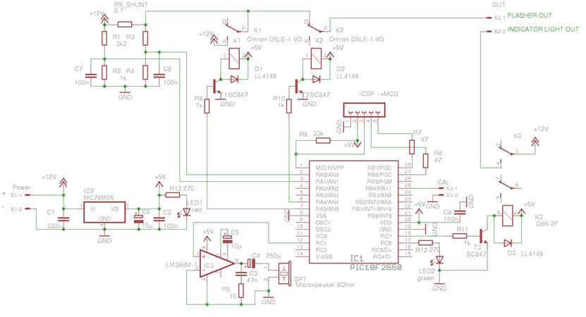
Schematic diagram
5.
Explanation
of the schematic diagram
(Refer to the schematic diagram).
R5_SHUNT is the shunt resistance through which the
current to light up the LED bulbs passes. This resistance should be carefully
designed, in such a way that the voltage difference before and after is still
big enough for the PIC’s built-in ADC convertor (which is only 10 bit) to be
able to measure it, even with LEDs that don’t use much current. So the value
should be high enough (e.g. 0.1 Ohms) but not too high, because when classic
light bulbs are used instead of LEDs, we don’t want the voltage drop to be too
high and we also don’t want the shunt to produce too much heat or burn up. The
shunt can for example be made of a heat wire from an old toaster.
K1 will assist in competing against heat production in
the shunt. The contacts of this relay are parallel to the shunt and the relay
is activated as soon as the trigger voltage difference is reached, and stays
activated for the remaining of the ON-cycle.
K2 is the actual flashing relay that will put off and
on the lights intermediately.
K3 is for driving the indicator light on the dashboard.
IC1 is the PIC microcontroller.
IC2 is for downgrading 12V to 5V needed for the PIC.
IC3 is for producing “blip-blop” sounds while
flashing.
6.
The
printed circuit board
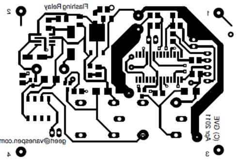
The pcb is designed for smd components and is double
sided.
Top side (mirrored):
Link to high quality
PDF (mirrored) of top side (use this for printing on a transparent)
Bottom side:

Link to high
quality PDF of bottom side (use this for printing on a transparent)
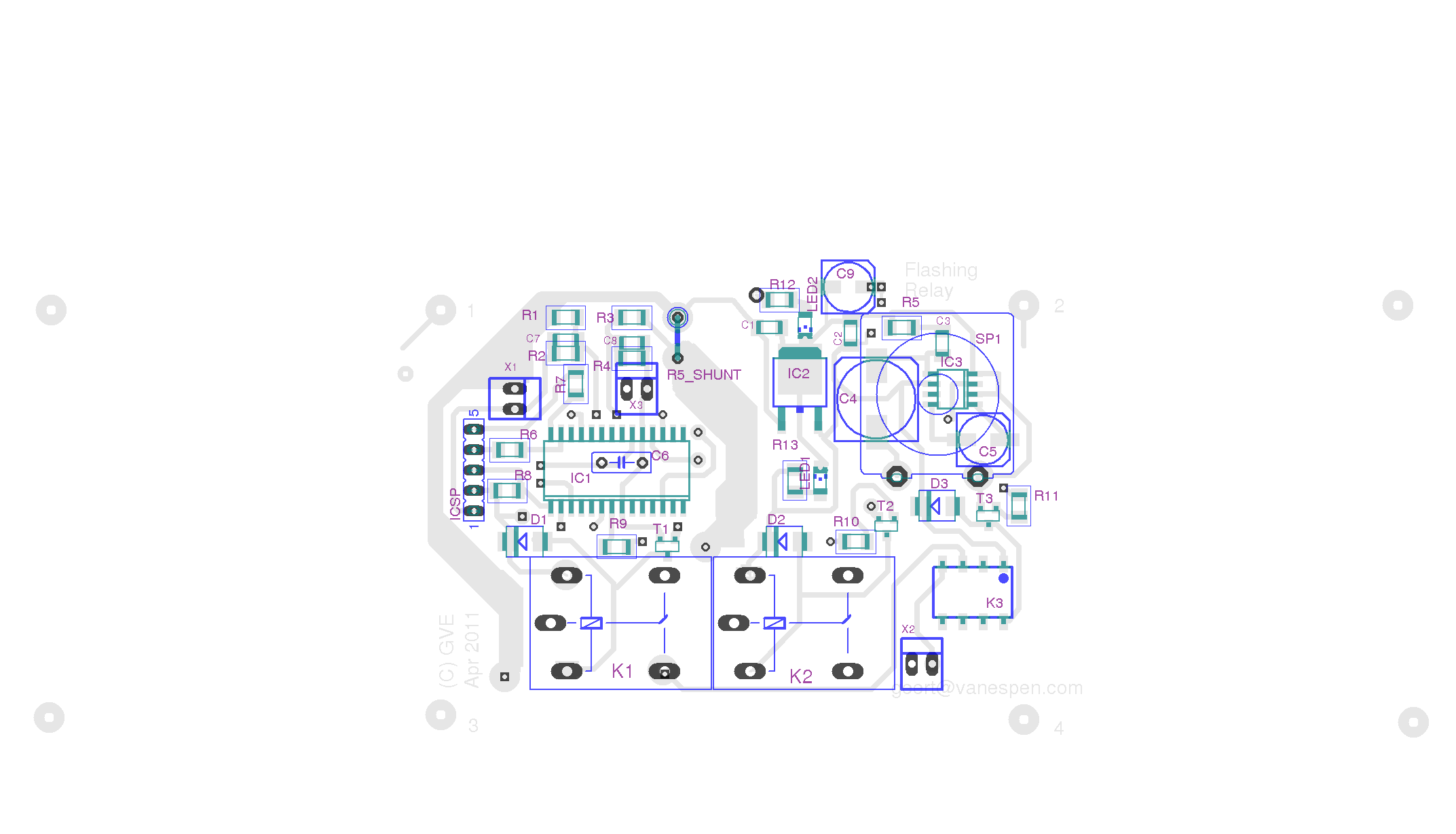
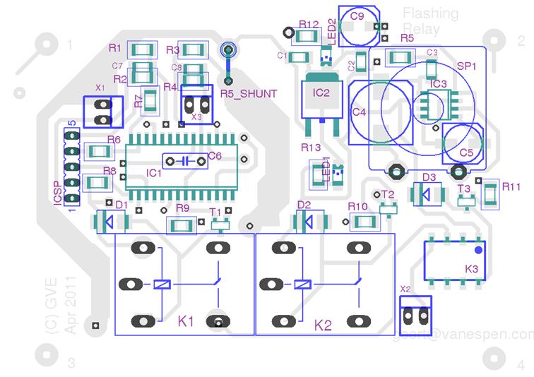
Some pictures of the PCB:
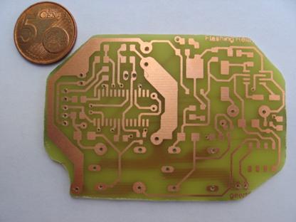
This is how the components
layout will look like:
This is the part list.
7.
Calibration
Before first use, the device must be calibrated. To
measure the voltage before and after the shunt, two ADC ports (AN0 and AN1)
together with to voltage dividers (R1/R2 and R3/R4) are used. Since resistor
values are not 100% accurate, the voltage dividers must be compared to each
other. This is called calibration.
To calibrate the device, make sure no lights are
connected to the output, and connect a jumper on X3 (short circuit). Then apply
power to the device, which will now start in calibration mode (shown by the green
LED flashing 5 times). After this, calibration is done and a pause of 2 seconds
(green LED off) is introduced followed by the LED again flashing a few times
(the number of flashes indicating the calibration value).
Disconnect power and remove the jumper on X3. The
device is now calibrated. The calibration value is stored in EEPROM for next
time usage.
8.
Programming
The software is written in C (PIC C18 from Microchip)
and compiled to a hex file.
It was first prototyped on a Dwengo experimental board
(http://www.dwengo.org).
Since this board uses a PIC18F4550, I designed two projects: one for PIC
18F4550 and one for PIC 18F2550 (the final design). The first one also uses the
Dwengo library to show some debug messages on the Dwengo LCD, the second one
does not need the Dwengo library.
You do not need the Dwengo board and library to build
this project, just the Microchip IDE and a PICkit2 compatible programmer will
do.
Zip file containing all source code, header files and
project files: link to MPLAB projects
Connection to a PIC programmer.
The ICSP connector must be (temporary) wired to a PIC
programmer, with the contacts in this order: -, +, VPP, clock, data. You can
use e.g. a PICkit2 compatible programmer.
9.
Customization
If you want to customize the software, have a look at KnipperRelais.c in which you can change various
defines:
MAXCOUNT_ON the
time for the light being on, in units of DELAY_TIME (more or less)
MAXCOUNT_OFF the
time for the light being off, in units of DELAY_TIME (more or less)
DELAY_TIME delay time in ms for the main loop
TRESHOLD1 sensitivity for the voltage drop
trigger
 Home
Home ![]() Back to Electronic
Projects
Back to Electronic
Projects