Charge limiter

This circuit is an extension for an "ordinary" battery-charger, the "cheap" kind whithout complicated
electronics. The extension takes care not to overcharge the battery by simply stopping the charge current
when a certain voltage is reached. If the voltage drops again, charging will be resumed.
The circuit uses the PIC16F873 microcontroller to keep things simple (little hardware needed, all functionality is
implemented in software). The PIC16F873 has an internal analog-to-digital converter, that's why I used this type.
Also, a Dallas Semiconductor DS1820 chip is used to measure the ambient temperature. The voltage-treshold is
temperature dependent.
In the circuit, there is no capacitor shown to stabilize the input power. If the charger used only contains
a rectifier, a capacitor must be added to smooth the voltage. Use a 1000 µF elco.
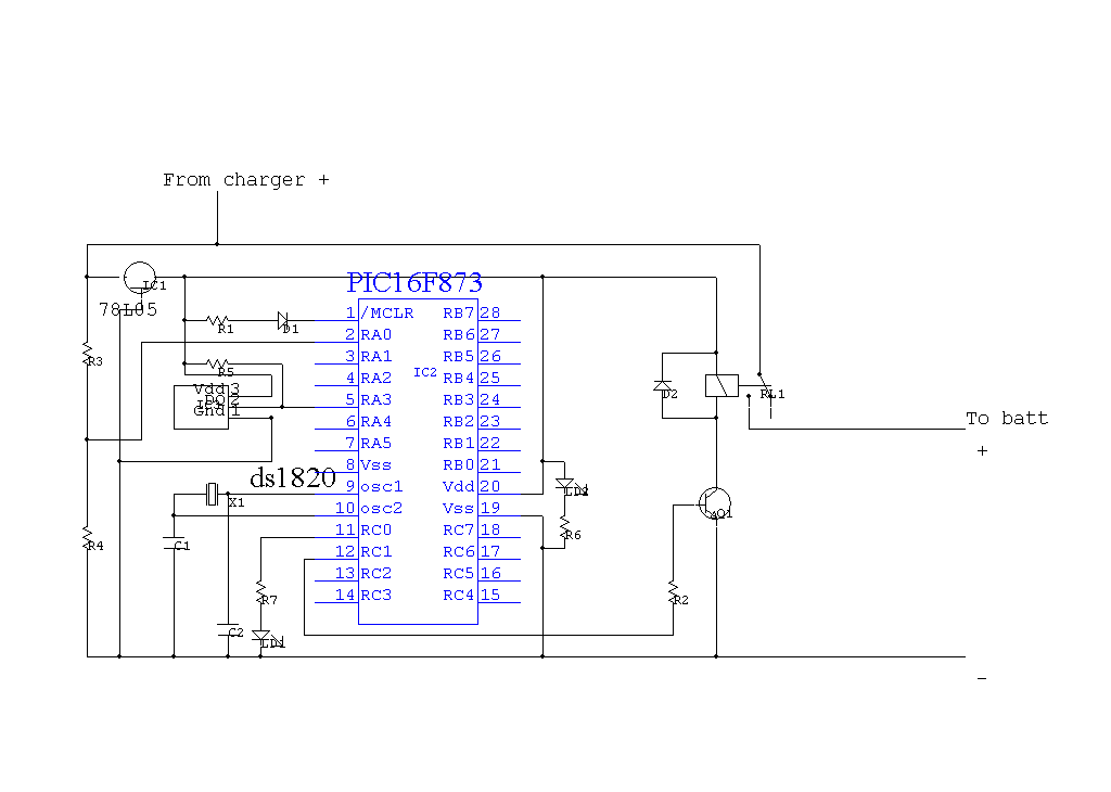
Schematic diagram of the charge limiter
List of components
Circuit explanation:
Port RA0 (configured as AD input) is used to measure the voltage of the charger using voltage divider R3/R4.
Port RA3 is used as a digital input/output to control the Dallas DS1820 temperature sensor. In the beginning of the
program, the relay is activated, ensuring battery and charger are connected which in fact enforces reading the
battery voltage and not the charger voltage. Depending the charge state of the battery, the software will decide
whether to release the relay. After a while the relay is activated again and the cycle will start from the
beginning.
Source code for this project
Features
Printed circuit board
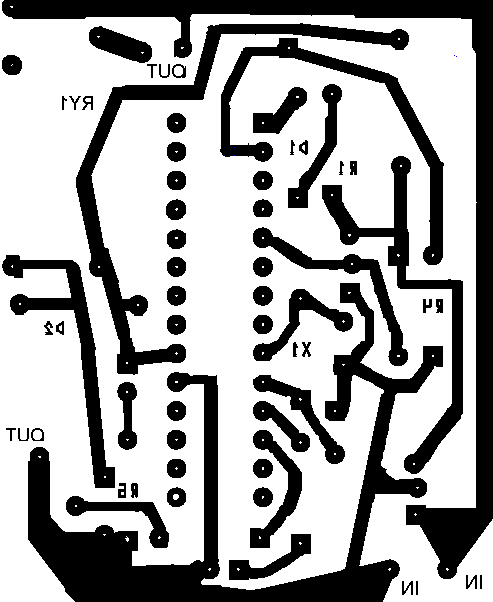
Copper side of the printed circuit.
|
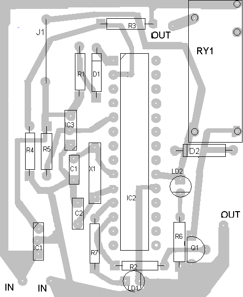
Components side of the printed circuit.
|
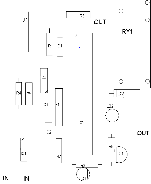
Components layout.
|
Download print-layout as Word 2000 document
Download print-layout as PDF
Picture
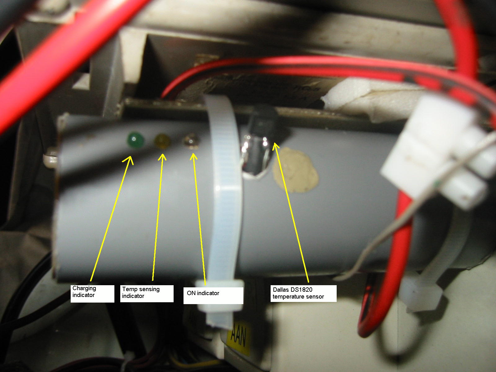
The device built into a plastic pipe, mounted under the original charger.
|
 Home
Home
 Back to Electronic Projects