Light switch
Home

This circuit features an automatic switch to put on or off a light. The light is switched on or off depending on darkness of the environment, random moments and time.
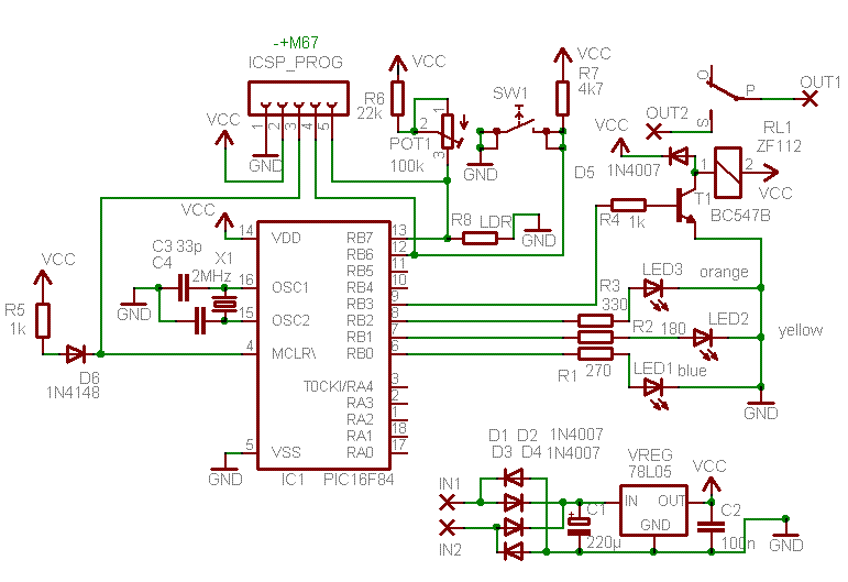
The device contains three led's, one pushbutton and a relay output.
The device has 8 modes. By pushing the pushbutton, the user scrolls through the modes. The mode you are currently in, is represented by the status of the leds.
Another nice feature of the device is that it saves the last used mode in EEPROM, so that when the mains power goes away and comes back up, the last mode used is back up again.
These are the 8 modes and their corresponding led status:
| Mode |
Description |
Blue led |
Yellow led |
Orange led |
| 1 |
The light is on.
|
off |
off |
on |
| 2 |
The light is off.
|
off |
off |
off |
| 3 |
The light switches on when it gets dark.
|
off |
on |
off |
| 4 |
The light switches on when it gets dark, but does not stay on longer than 6 hours.
|
off |
on |
on |
| 5 |
The light switches on and off randomly.
|
on |
off |
off |
| 6 |
The light switches on and off randomly, but only when it gets dark.
|
on |
on |
off |
| 7 |
The light switches on and off randomly, but only when it gets dark, and this is limitid to about 6 hours.
|
on |
on |
on |
| 8 |
Light sensitivity adjust mode. During this mode, you can easyly adjust the light sensitivity and see the effect on the light going on or off, whithout hysteresis (slow down). In the other modes dealing with the environment light, there is of course always some kind of hysteresis to prevent the light being fastly switched on or off when the evening falls.
|
flashing |
flashing |
flashing |
One possible use is to use of the device to scare thiefs by use of the random effect when the light switches on and off.
The light sensitivity can be adjusted by means of POT1.
You will have to add a transformer (about 8 to 12 VAC secondary) to connect the device to the mains, and some wiring to relay 1 and a 230V light to get the thing complete.
This circuit is based around the PIC 16C84 (or PIC 16F84) microcontroller. This chip is actually a small computer contained
in a single chip, including RAM memory, EEPROM, I/O ports, CPU and so on. When you buy this chip, it comes empty with no
program on it. You have to compile the source code and download the resulting machine code into it, using a PC and a small
programmer attached to the parallel port of the PC and the chip. To get yourself familiar with this stuff, I suggest
you first read this link:
Getting started with microcontrollers.
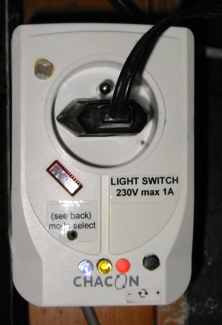
Picture of the finished project, build into a dismantled lightning protector:

Schematic diagram:

List of components
Source code for this project
PCB layout and components setup (PDF)
PCB layout and components setup SMD version (PDF)
Link to Eagle schematic diagram
Link to Eagle schematic diagram, smd version
Link to Eagle layout
Link to Eagle layout, smd version
 Home
Home
 Back to Electronic Projects


 Home
Home
 Back to Electronic Projects