Remarks about this project:
The input labelled 'to waterpump' can be used to automatically switch on the device, for instance when a pump starts
running. The input can be connected parallel to the pump. If not used, ground this input to avoid problems.
The LCD display module is a standard Hitachi-compatible module available everywhere (16 chars x 2 lines with background
light).
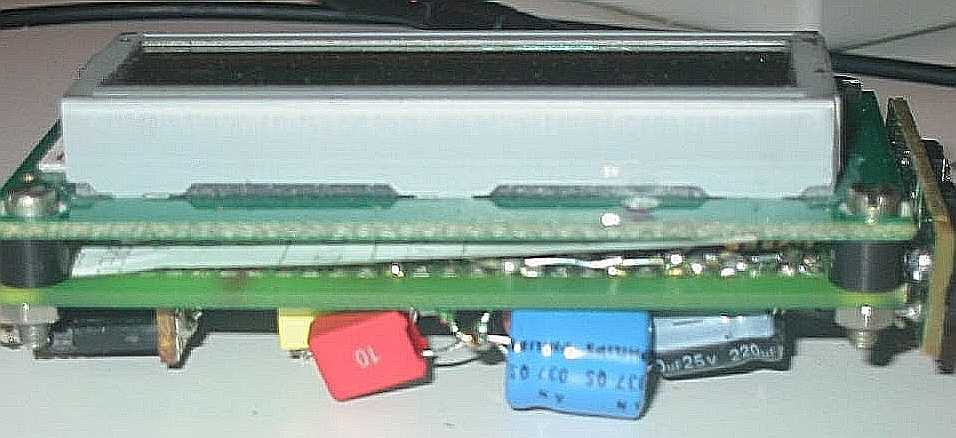
This module has it's own circuit board, I "sandwiched" this with my own circuit board (exp board) to form a nice
single unit, the final display module (with PIC).
Don't forget the wire bridge (points marked with * must be connected together).
In the circuit for the sensor module, the connections to ground and plus are not drawn for the 5 IC's, to keep
the diagram more comprehansible. Don't forget these.
Adjusting: put 4 sensors in water (and also the common wire). Adjust P1 so that 4 blocks are shown on the LCD.
Schematic diagram of the sensor-circuit (the "Elektuur" device)

List of components for the sensor-device
PCB layout for the sensor-device
Component setup for the sensor-device
Circuit explanation:
IC4 is a counter/oscillator combination and is the key element in the circuit. The oscillator outputs its
AC signal on pin 7. This signal is lead (through voltage divider R3/R4) to pin 3 of IC5 (multiplexer IC) which
is used as an input. The same signal is also lead to the rectifier/demodulator build up with D1/R1/R5. The resulting
rectified signal is compared (with IC2, an opamp) with a constant voltage. If a selected electrode is under water,
there will be an extra load on the AC signal, which causes the output of the demodulator to drop a little bit. The
comparator will react by changing its output level. All this takes a fraction of a second because the multiplexer
will only handle one electrode at a time by connecting the AC signal to the selected electrode.
The multiplexer doesn't only select the measuring electrodes, but also (through IC3, a BCD to decimal decoder) the
eight outputs of the circuit (pin 0..7 of IC3). Using the 'enable' input of IC3, powered by the output of the
comparator, the status of each electrode is passed through.
The two NAND gates (IC6) close to the output of the comparator and to the "enable" input of IC3 are used for
compensation of the fact that the measured value of each electrode is slowed down a bit by C1/R5.
On each output a constant high level can be found if the corresponding electrode is dry, and short pulses of low
levels will be found there if the corresponding electrode is lying under water.
Current consumption of this circuit alone, if LED is removed, is about 0.660 mA.
Schematic diagram of the display-circuit

List of components for the display-circuit
Circuit explanation:
The connector marked "+-12345678" is connected to the other circuit (the Elektuur sensor circuit). On the "+",
a plus 5 volt tension will be put by port RA0 of the PIC16F873 microcontroller. This will only happen if the
device is put on (or is automatically put on) and after the LCD module and the processor itself are
stabilized (cfr. source code). In all other cases, a 0 volt level will be found here. The "-" is there only to
connect the grounds of both circuits together. Connections "1" trough "8" are connected (using flat cable) to
the outputs of the Elektuur circuit. On this circuit, they are also connected to port C of the processor, which
is configured as all inputs. The software in the microcontroller will constantly poll port C, this means it is
checking (during about 5 ms per electrode) if a selected electrode has been low at least once during the
period (= electrode under water).
The LCD module is a typical character based (16 x 2) Hitachi compatible LCD module available in many places. It is
controlled using 4-bit mode from the microcontroller.
Transistor TR1 is used to power the LCD backlight LEDs. This takes about 110 mA of current, which cannot be handled
directly by the PIC.
Potentiometer VR1 is for adjusting the LCDs contrast.
The circuit is meant for RV's and is connected to the light battery (12 V), so it shouldn't take to much current.
By using a "low drop - low quiescent current" voltage regulator (LP2950 5V or if you can't find this one, the
4805CV) the circuit takes only about 1 mA in stand by mode (this is when the PIC is in 'sleep' mode so the LCD
module, background light and the Elektuur circuit are off). When everything is on, the current consumption is
about 120 mA. If after a while (about 5 minutes) the background LEDs are switched off by the software but the LCD
is still on, the current consumption is about 9 mA (both circuits together).
Some pictures

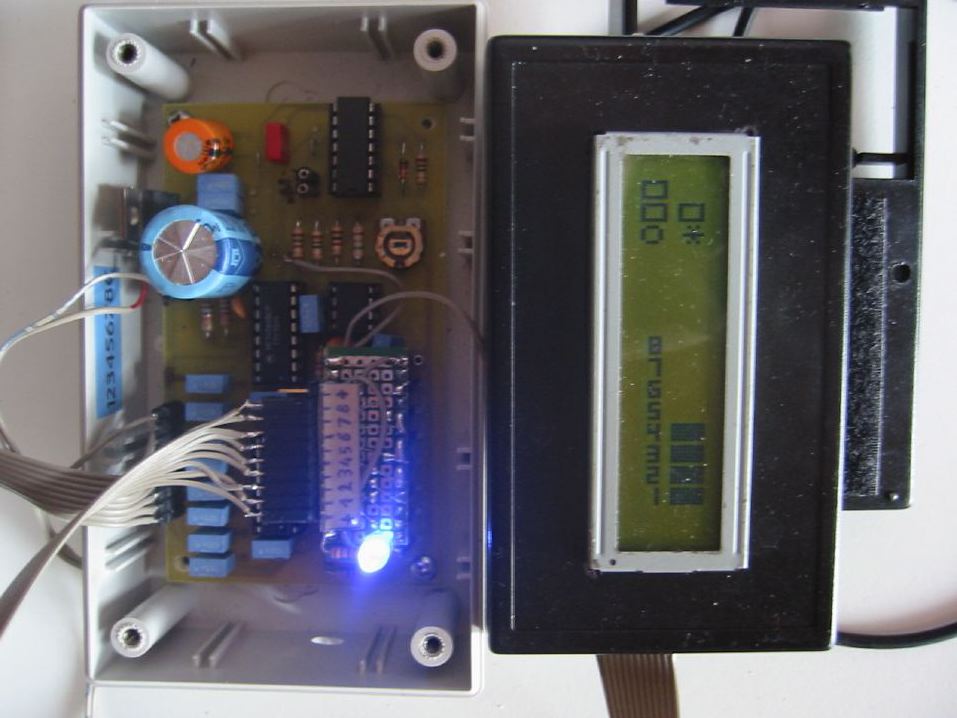
Both devices are connected using flat cable. |

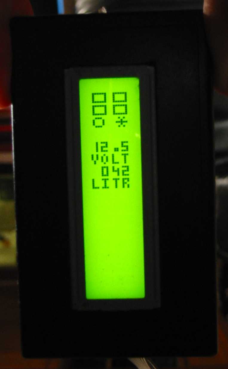
Vertical display with backlight. |

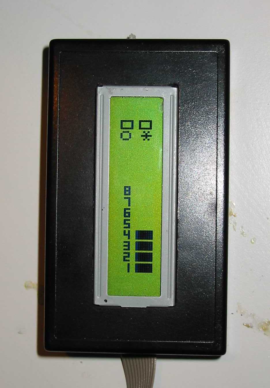
Bar graph display. |

LCD module and PIC circuit "sandwiched". |