Universal timer


This circuit is a versatile timer, just like the ones you can buy. But this one has some interesting features. You can program 14 times, each as an on, off or random program. There are hourly, dayly, weekly programs as well as a weekend program. It can also have a programmed action when it gets dark, or when it gets light. Several of these features are combinable.
This project is also a replacement for the following other (previous) of my projects found elsewhere on this site:
"Garden light switch", "Random switch" and "Light switch". It has all features of all three of these projects and more!

Here are a few examples of use:
To mislead potential burglars, put on a light when it gets dark, then put it off and on in a random way, during six hours.
Put on a light every hour on the hour and put it off after 5 minutes.
Use as alarm (with snooze function): every weekday at 7:00 hours put on the radio and put if off at 8:00 hours.

Light sensitivity can be set, as wel as the duty cycle for the random action (this means the average percentage of time the relay will be on when random mode is active).
The circuit uses the PIC16F873 microcontroller to keep things simple (little hardware needed, all functionality is implemented in software). The PIC16F873 has an internal analog-to-digital converter, which in this case is used for measuring the amount of light (using an LDR as a sensor).

Building tip 1: change C2 (33pF capacitor) with a variable capacitor of about 68pF. This way you can adjust the accuracy of the clock by varying this capacitors setting, and so you don't need to change the software to adjust the accuracy (for software adjusting: see program listing).
Building tip 2: if you can't find the LP2950 5V regulator you can also use the popular 78L05 regulator.
Building tip 3: the power supply is not drawn on the schematic diagram. You can just use a 6V transformer (of about 1 VA) and a bridge rectifier (or 4 diodes type 1N4148) together with a 470 µF capacitor.


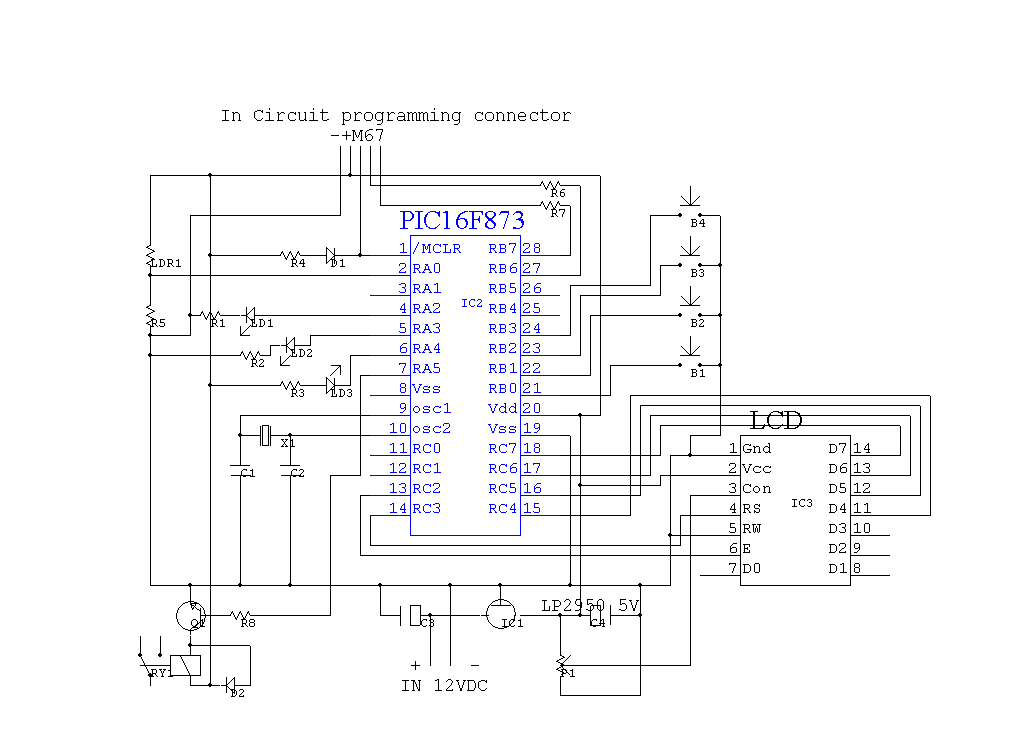
Schematic diagram of the universal timer

List of components

Circuit explanation:


Port RA0 (configured as AD input) is used to measure the voltage resulting of voltage divider LDR1/R5 which is proportianal to the amount of light. Port RA2 to 5 are outputs for the 3 leds and 1 relay.
Potmeter P1 is for adjusting the LCDs contrast.


Source code for this project


Features/short user manual


User manual (PDF file)


Pseudo code (Word 2000 document)


Picture's
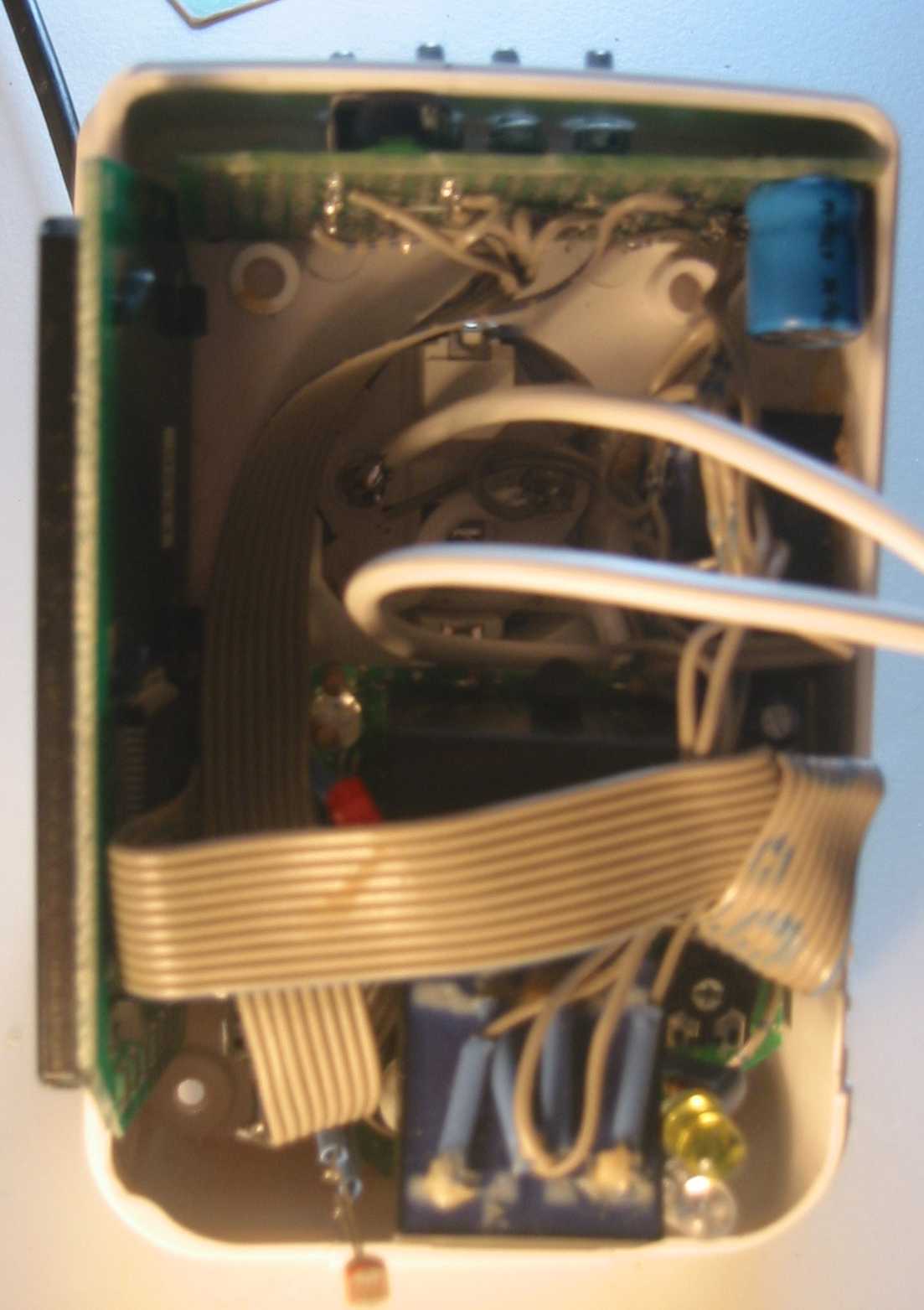
Picture of the device opened up.

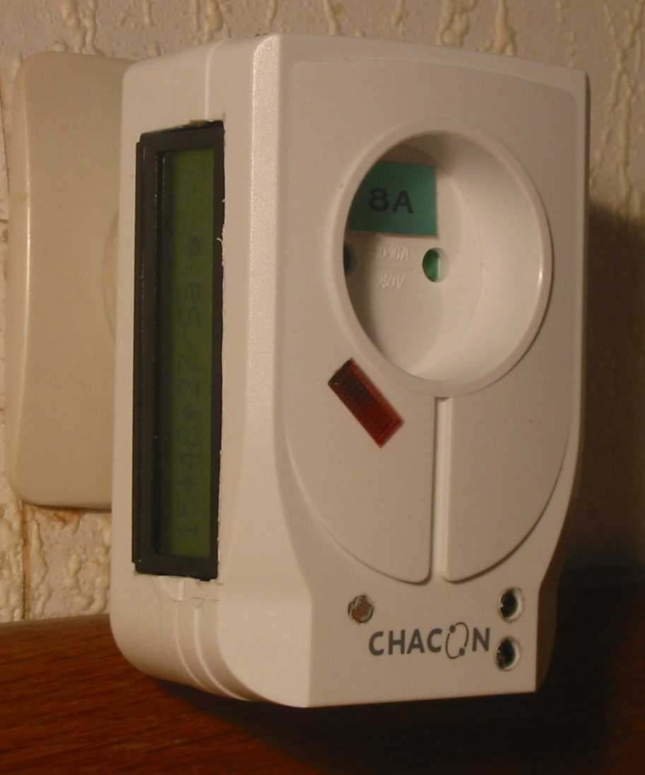
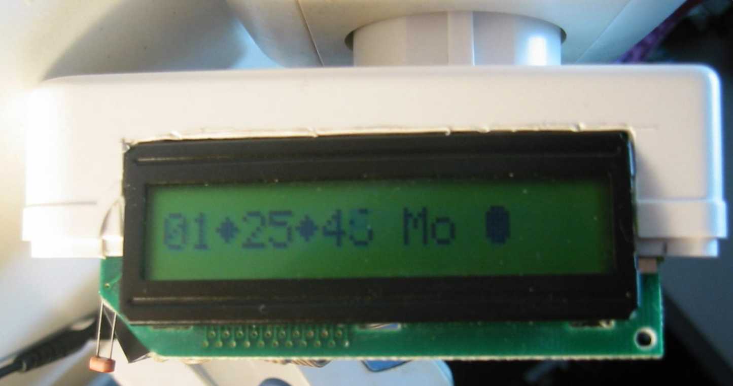
The device built into the housing of a modified mains protector. The LCD display is mounted sideways because of it's size.
The LDR (brown) is visible left below (pointing downwards).

On this picture, you can also see that the device is plugged into a wall socket on top of the picture.

The display in regular time keeping mode, showing 1:25:45 hours Monday, seconds just moving to 46 when the picture was taken.

Another look inside.

The device opened up. Below (a little left from the center) is the LDR sensor. Right below you can see the yellow LED en the blue LED (which looks like a white one). In between is a small (0.33 VA) transformer. A second transformer, connected parallel to the first one, seemed necessary (right above, below the blue elco) to deliver enough power for the 8A relay (just below the thick white wire).
Above the yellow LED you can see the potmeter for adjusting the LCD's contrast.

White leads are for 230V connections.

On the left, the LCD module.

The horizontal flat cable connects the LCD module to the main circuit. The other flat cable connects the upper circuit (with buttons, rectifier and elco) to the main circuit.
The main circuit is not quite visible. The microcontroller on it is also invisible. It is located just below the horizontal flat cable.


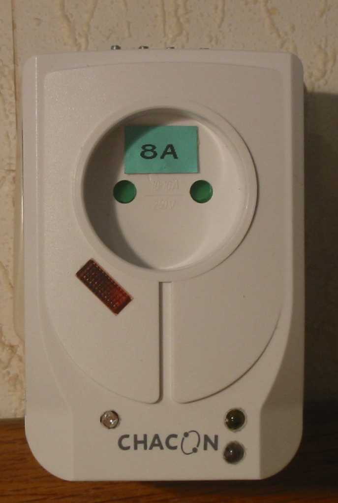
Picture of the finished device.

Front view of the device plugged into a wall socket.
The LDR is visible left below.

Yellow and blue LEDs right below. Red LED in the middle, left.

On top, the buttons.

Another look of the finished device.

A side view of the finished device, plugged into the wall.

The LCD display with green background on the left.

  Home         Back to Electronic Projects